TopicsLatest information
2026.04.20
Introduction to FPC Design : Key Points for Defining the “Flexible” and “Rigid” Sections in FPC Design – Part 1
ColumnOne of the first and most important steps in Flexible Printed Circuit (FPC) design is to clearly determine which areas are intended to bend and which areas must remain rigid.
If the boundaries between these areas are left ambiguous, design-related problems such as wire breakage or assembly defects can occur.
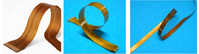
An FPC is not “entirely flexible.”
As a reminder, an FPC should not be designed as a circuit board that bends everywhere.
It is essential to intentionally design both flexible areas and rigid areas for different purposes.- Flexible areas: Sections intended for bending, folding, or movement
- Rigid areas: Sections for component mounting, through-hole placement, and connector insertion
Clarifying these areas at the earliest design stage is critical.
Design considerations for the flexible areas (bend regions)
Roles of flexible areas:
- To allow folding within an enclosure
- To follow the movement of mechanical parts
- To temporarily change shape during assembly
What to avoid in flexible areas:
- Placing components
- Adding through-holes
- Changing trace width or angle
Basic design rules:
- At the boundary between rigid and flexible sections, and in the bend region itself, routing should run straight and perpendicular to the boundary or bend line. Angled traces cause uneven stress distribution during bending, which can lead to conductor breakage.
- Keep conductor widths as uniform as possible. Variations in line width concentrate bending stress and increase the risk of breaks. When width changes are unavoidable, use a fillet to transition gradually.
- Keep traces as straight as possible. When bends are required, use smooth curves instead of sharp right-angle turns.
- Even for unused copper areas such as GND planes, avoid sharp corners at the copper edges—always add a radius to reduce stress concentration.
Design guidelines for the rigid sections will be covered in the next part.
#FPC #My first FPC #FPC design #Flexible area
