
TopicsLatest information
2026.07.31
Introduction to FPC: Key Points for TH and LVH design - Part 1
ColumnIntroduction
Through holes (TH) are relatively large holes formed by mechanical drilling, with electrical interconnection achieved through copper plating. This is a well‑established and highly reliable process. Laser Via Holes (LVH), on the other hand, are micro‑vias created using laser drilling. They are well suited for blind vias and high‑density interconnections; however, plating quality, surface planarity, and process control have a direct impact on overall product reliability.
- Where each structure (TH or LVH) should be used
- The manufacturing capabilities of the selected supplier, including minimum hole diameter and achievable plating thickness tolerances.
Mechanical Considerations: Stress and Misalignment
Avoid placing TH in bending areas
Placing THs or LVHs in flexing zones significantly increases the risk of copper plating or pad delamination due to bending stress, which may lead to open circuits.
For FPC designs, always verify the relationship between bending radius and hole location.-
Pad geometry and filleting (radius design)
Manufacturing misalignment can cause pad breakout. As a general rule ;
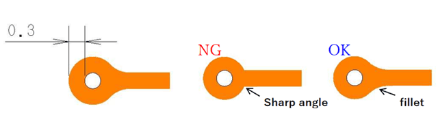
- Design pad diameters to be 0.4–0.6 mm larger than the hole size to ensure an annular ring width of 0.2–0.3 mm after drilling (for both TH and LVH).
- Use teardrop shapes or fillets (R) at trace‑to‑pad connections to reduce stress concentration.
-
Coverlay opening design
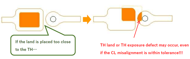
Since the process sequence involves drilling TH (or LVH) → copper plating → circuit patterning → coverlay lamination, it is critical to carefully design the clearance between Coverlay openings and THs (or LVHs). Improper spacing can result in hole(s) exposed from the coverlay opening, leading to reliability issues.
Electrical and Thermal Considerations
Allowable current for TH
The allowable current through a TH depends on its diameter and plating thickness. Typical design guidelines are ;
Φ0.3mm : approx. 300mA
Φ0.5mm : approx. 500mA
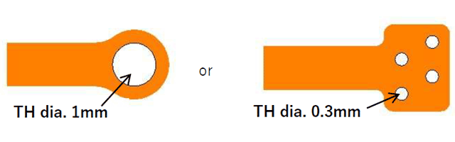
Φ1mm : approx..1A
Power lines or high‑current paths should be;
- Apply sufficient larger hole or thicker plating thickness or
- Implement multiple holes (or vias) in parallel to secure appropriate current capacity
For the 1A current path
#FPC #My first FPC #FPC design #Rigid area #Stiffner
