Functions of FPC
Impedance control FPC
Signal lines requiring impedance control (example)
Single-ended impedance control
| Signal lines | Single-ended impedance (example) |
|---|---|
| Antenna circuit | 50Ω , 75Ω |
| Analog circuit | 50Ω , 75Ω |
Differential impedance control
| Signal lines | Differential impedance (example) |
|---|---|
| USB | 90Ω |
| HDMI | 100Ω |
| LVDS | 100Ω |
| MIPI | 100Ω |
| PCIe | 100Ω , 85Ω |
| S-ATA | 100Ω |
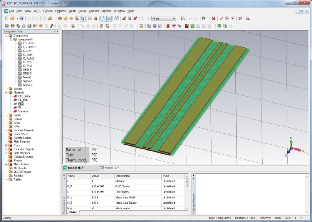
Fujikura Printed Circuits can perform simulation based on the FPC material structures and your required circuit impedance value, in order to recommend the best FPC circuit design for impedance matching.
We will also make a prototype FPC to measure the circuit impedance and verify the circuit design.
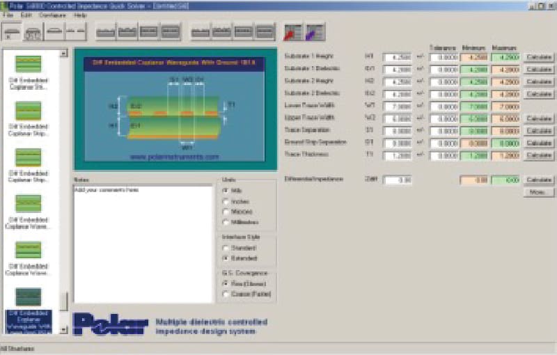 Impedance simulation (by Fujikura Printed Circuits Ltd.)
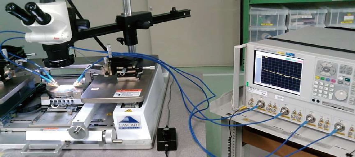 Impedance measurement (by Fujikura Printed Circuits Ltd.)
Structure
Compatible signal transmission line structures
- Co-planar
- Microstrip
- Strip
- Structures with various shielding materials, etc.
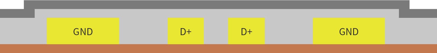
| Cross-sectional structure (example of differential transmission line) | |
|---|---|
| Co-planar line |
Formed with single-sided FPC
|
| Microstrip line |
Formed with double-sided FPC

Formed with single-sided FPC + shielding layer 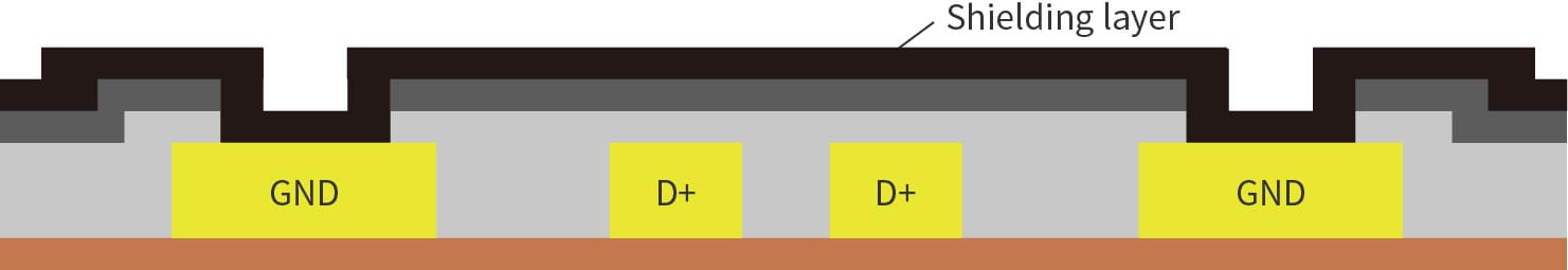
|
| Strip line |
Formed with 3-layer FPC
Formed with double-sided FPC + shielding layer 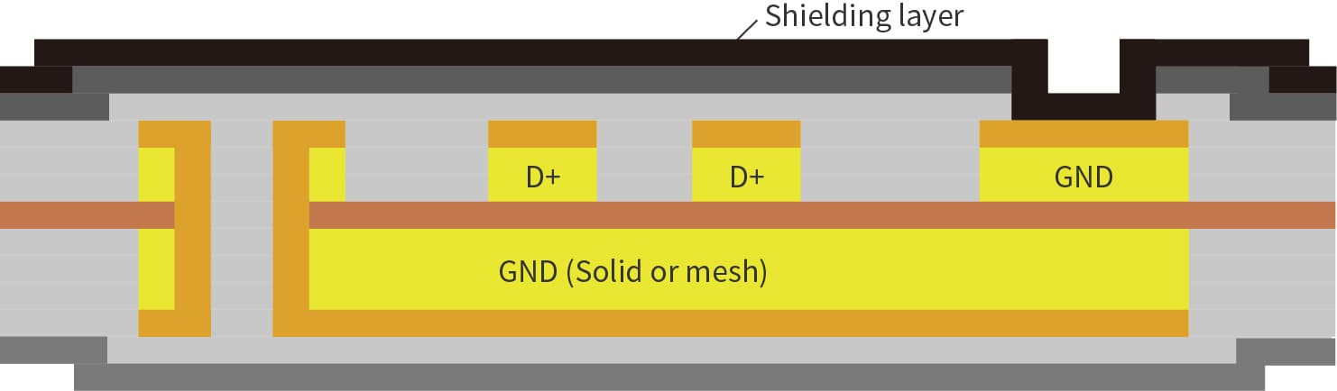
|
Low Dk (Dielectric constant) / Df (Dissipation factor) FPC
 High speed transmission FPC
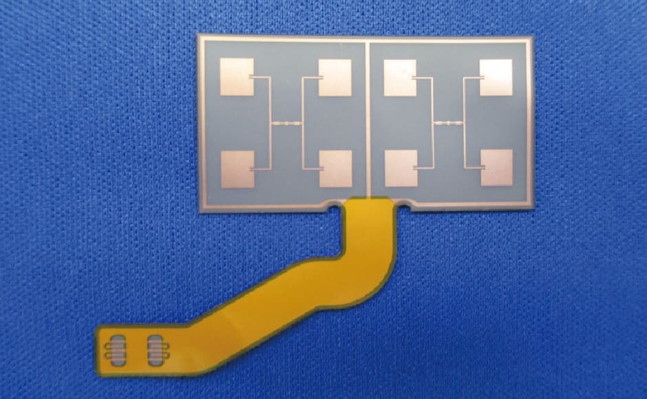 28GHz patch antenna FPC
For FPCs handling high-frequency/high-speed signals, we need to consider the high-frequency characteristics of the insulation materials (base film, coverlay, adhesive, etc.) to avoid attenuation of signal transmission. The graph below shows attenuation measurements for high-frequency/high-speed signals with different insulation materials
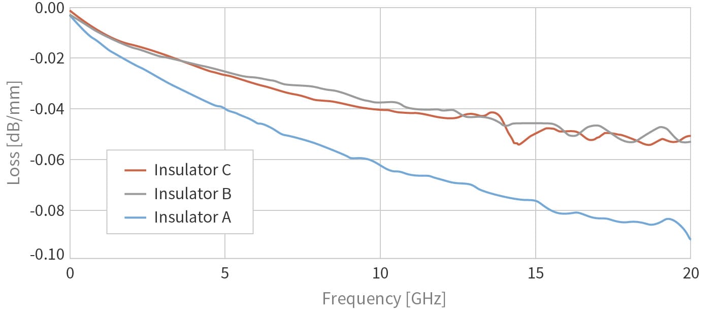
Fujikura Printed Circuits can provide all kinds of high frequency/high speed transmission FPCs.
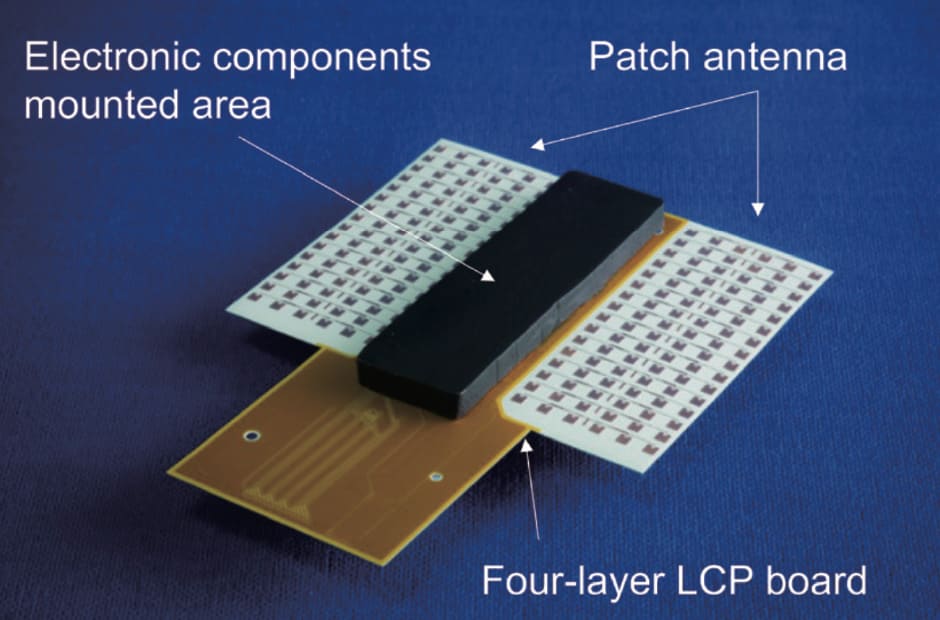
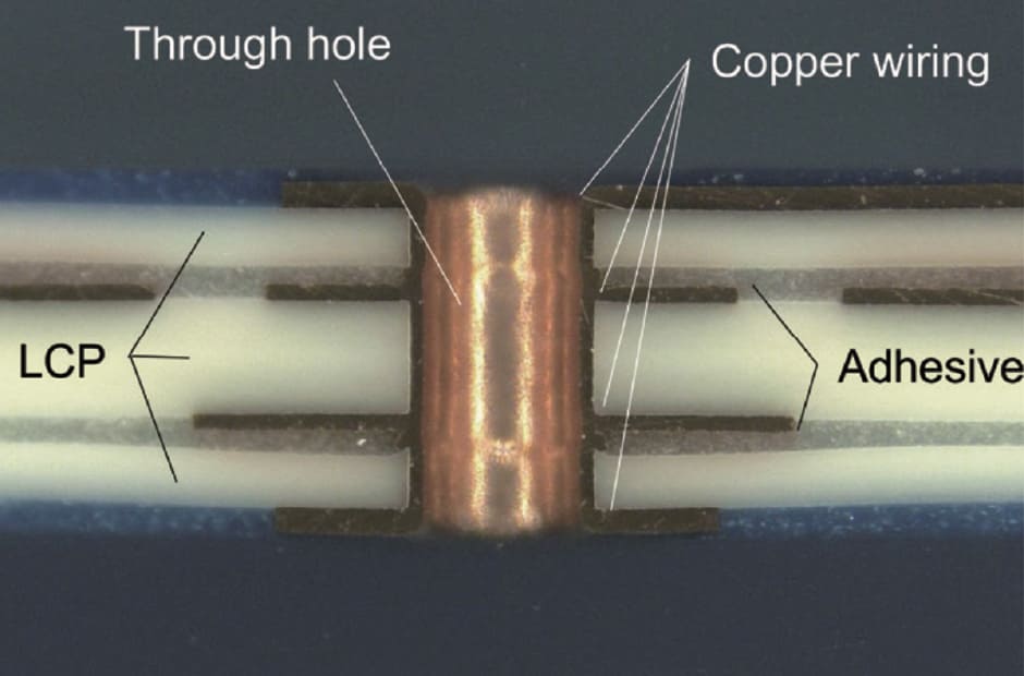
60-GHz antenna FPC appearance and cross-section
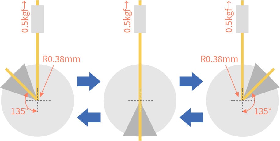
Bending durable FPC
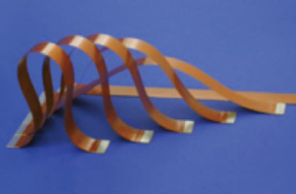
Because they are made from highly flexible films and copper foil, FPCs can be used in conditions requiring bending strength. Fujikura Printed Circuits can provide bending durable FPCs to suit your requirements.
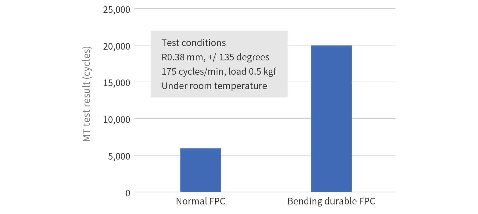
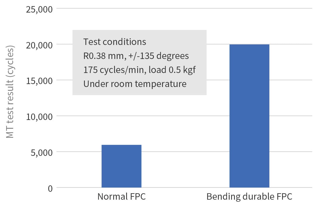
[Bending performance example 1]
Material configuration
- Coverlay film: Polyimide 12.5 µm thickness + adhesive
- Base film: Polyimide 12.5 µm thickness
Test method
- MIT bending test
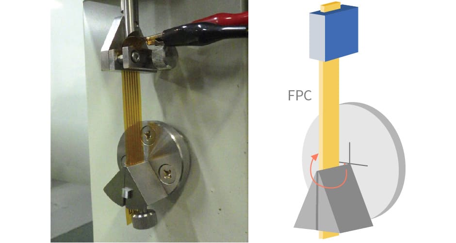
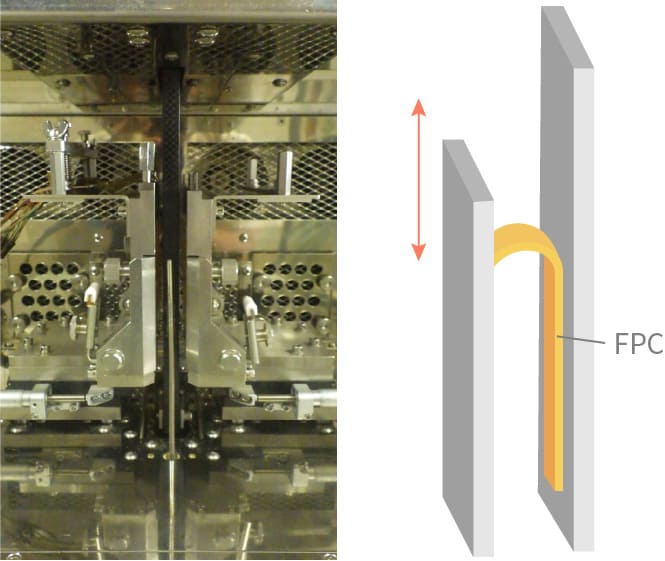
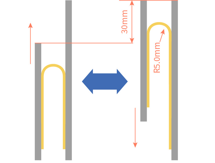
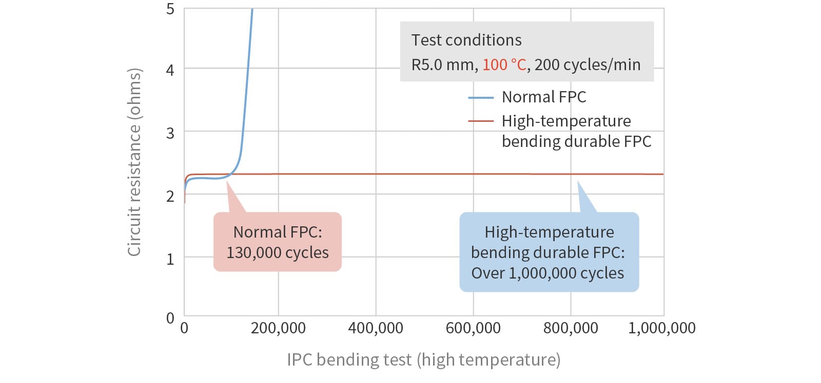
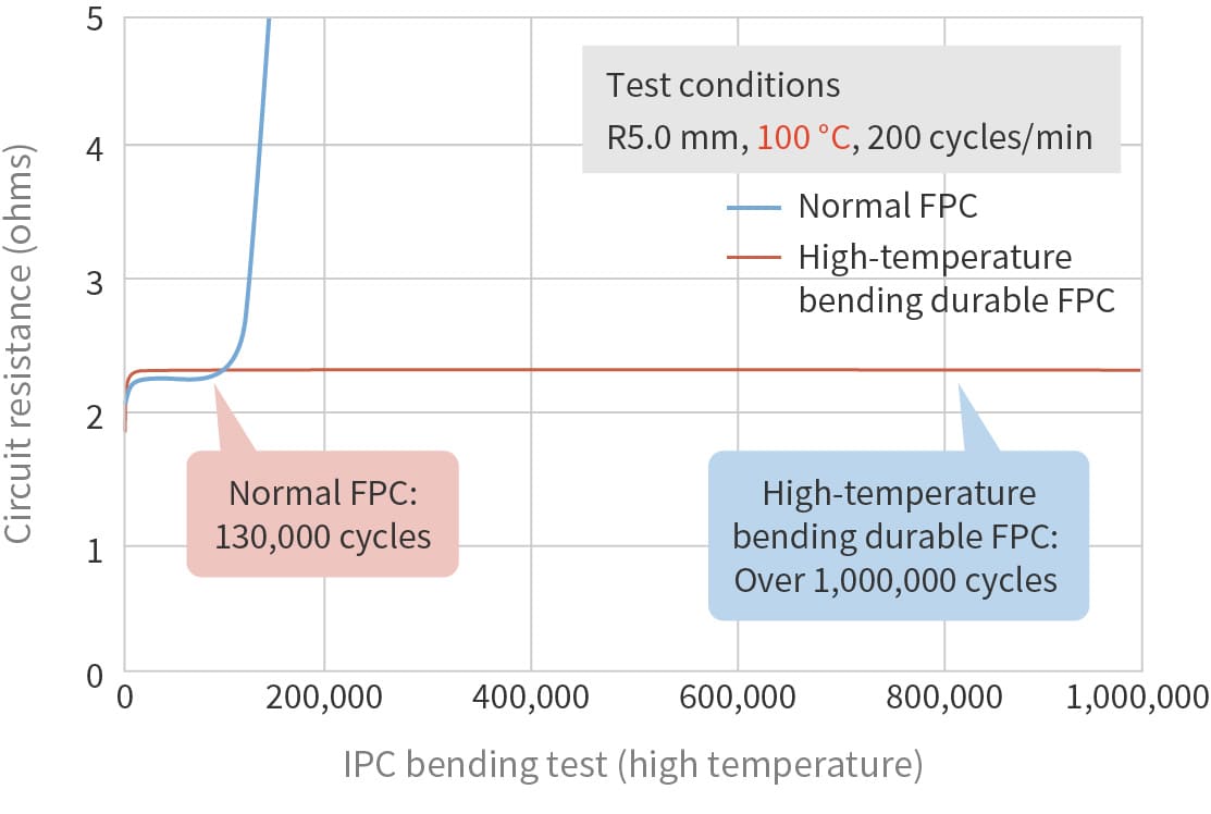
[Bending performance example 2]
Material configuration
- Coverlay film: Polyimide 25 µm thickness + adhesive
- Base film: Polyimide 25 µm thickness + adhesive + copper foil 35 µm thickness
Test method
- IPC bending test (high temperature)
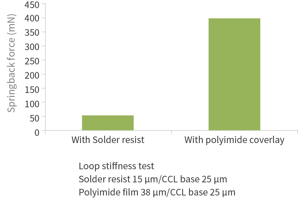
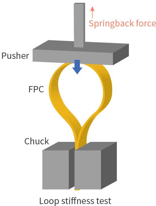
Low springback FPC
By applying photo imageable solder resist to the surface insulation layer, we can provide FPCs with high flexibility and formability compared to conventional FPC. This makes it easier to integrate the FPC into lighter, thinner, and smaller electronic devices, and helps to improve the quality of devices that require lower spring back performance (such as wearable devices).
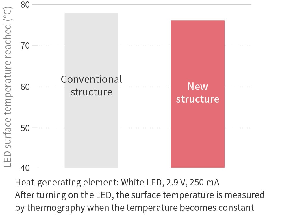
High heat dissipation FPC
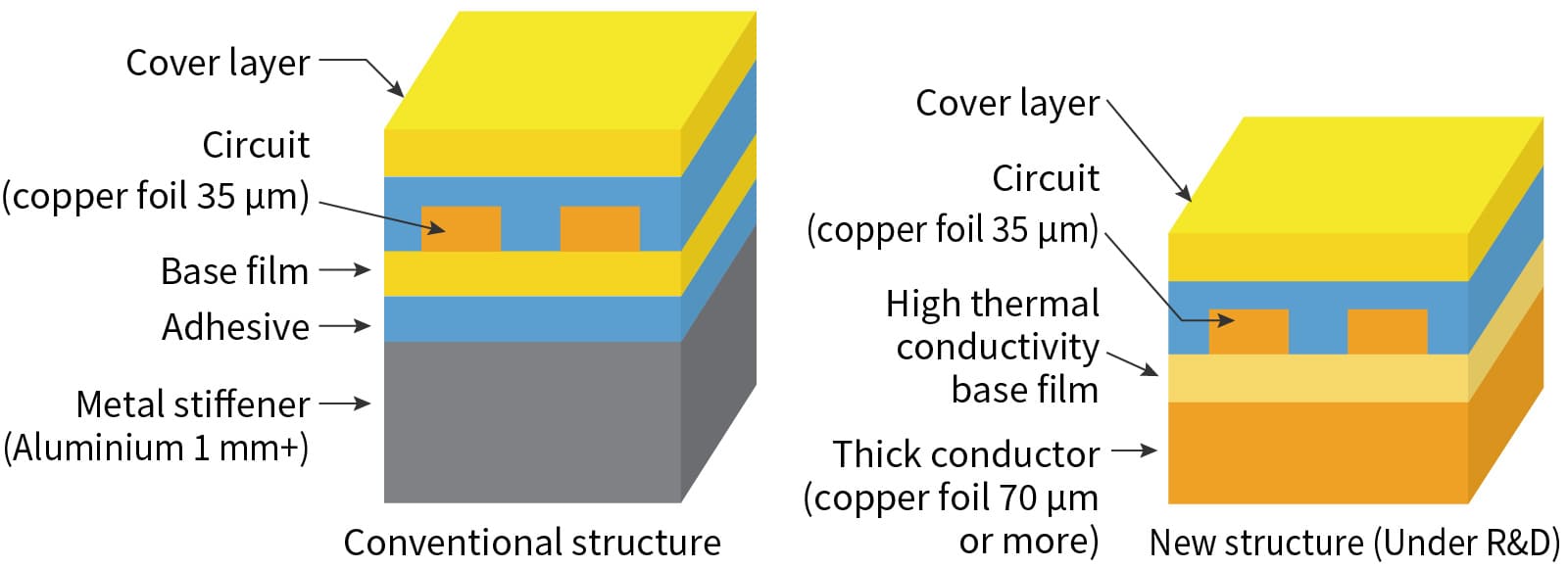
When heat-generating components such as LEDs are mounted on the FPC, a heat dissipation structure is required to allow heat to dissipate from the components. Heat dissipation is usually achieved by methods such as bonding a metal stiffener to the back of the component mounting area using adhesive. We have developed a new method using double-sided copper foil CCL (copper clad laminate) with a wiring layer on one side and a thick conductor heat dissipation layer on the other side, enabling heat to be dissipated from components without the use of metal stiffener.
By using a material with high thermal conductivity for the base film of the CCL, we have produced a 70 µm heat dissipation layer which achieves heat dissipation performance equivalent to or better than a metal reinforcing plate stiffener of thickness 1 mm. As well as providing heat dissipation performance equivalent to or better than the conventional solution, this new solution offers additional benefits like bendability, and also reduces thickness, weight, and cost. This solution is expected to be applied to all kinds of FPCs where heat dissipation is required.
[LED surface temperature with conventional structure and new structure]
[Schematic diagram of heat dissipation FPC structure]
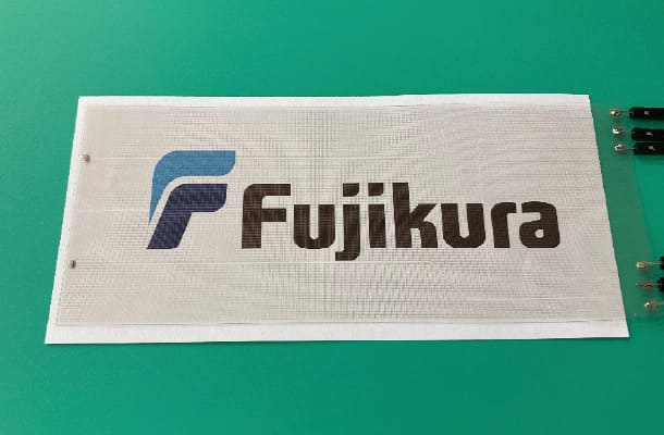
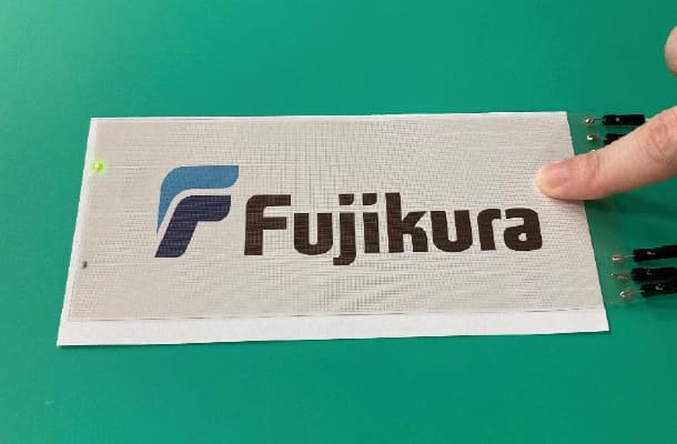
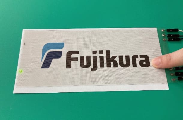
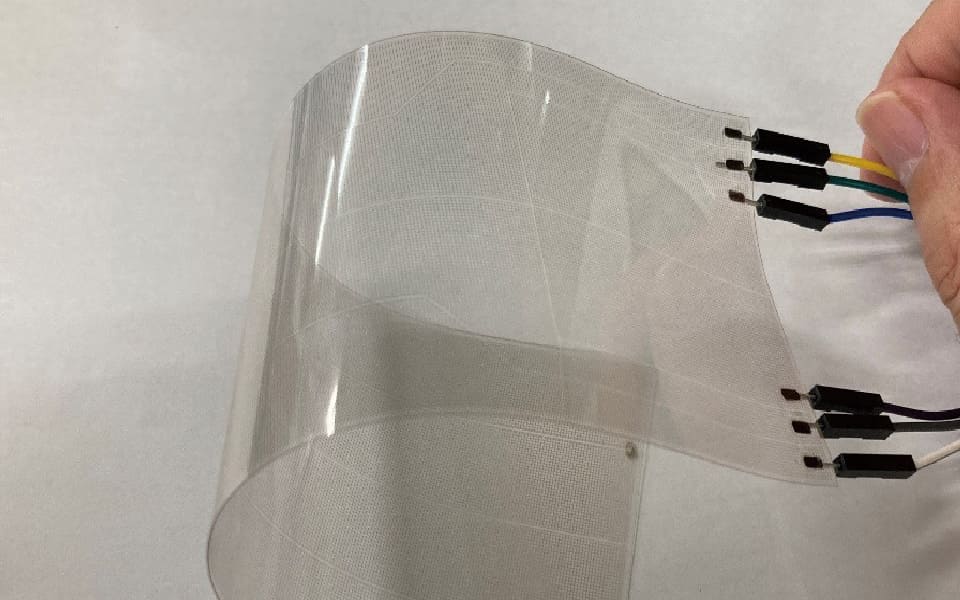
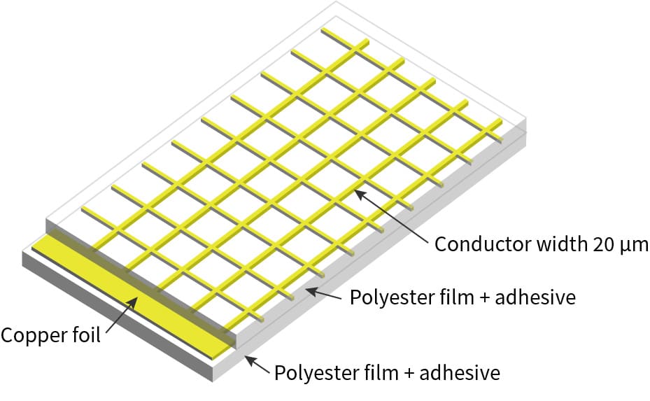
Transparent FPC
By wiring on a transparent polyester film, we can provide an FPC that blends in with the design of the device.
Shielded FPC
With increasing levels of functionality, the FPCs used in electronic devices need to handle high-speed signals with high-density wiring.
And as devices become smaller, signal lines are now wired closer together.
Under these conditions, noise controls are often required.
Fujikura Printed Circuits can provide shielded FPCs with various structures.
[Example of FPC electric field monitor (simulation)]
Insulator: 25 µm thickness, Dk(dielectric constant)=3.3, Df(dissipation factor) =0.003
Cross-sectional direction
| No shield | Single-side shield | Double-side shield |
|---|---|---|
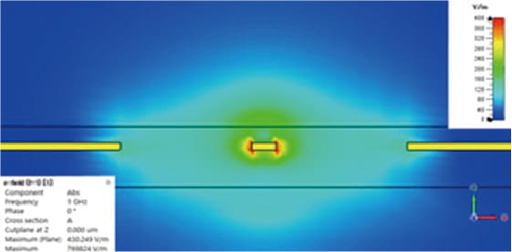 Electric field leakage in both directions
|
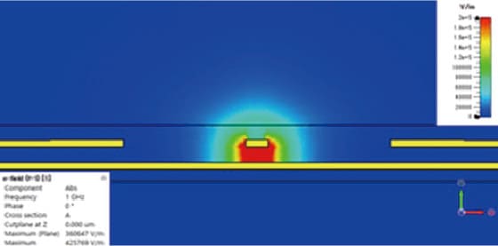 Electric field leakage in upwards direction but Strength is reduced
|
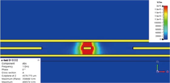 No electric field leakage
|
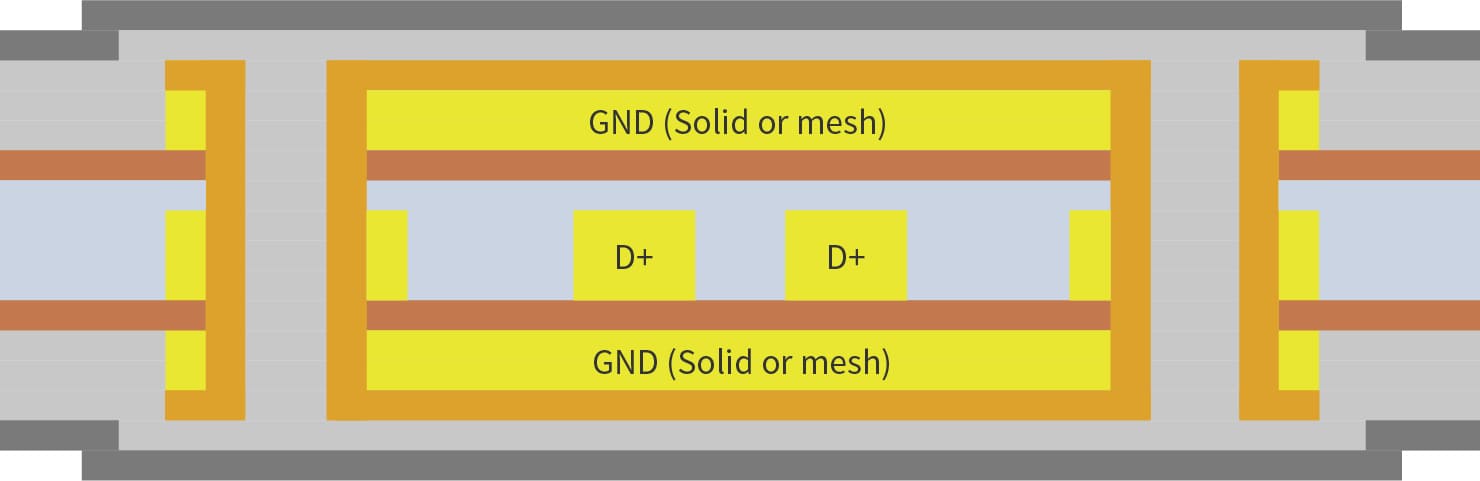
[Structure of shielded FPC (example)]
| Cross-sectional structure | |
|---|---|
| Single-side shield |
Formed with double-sided FPC

Formed with single-sided FPC + electromagnetic shielding layer 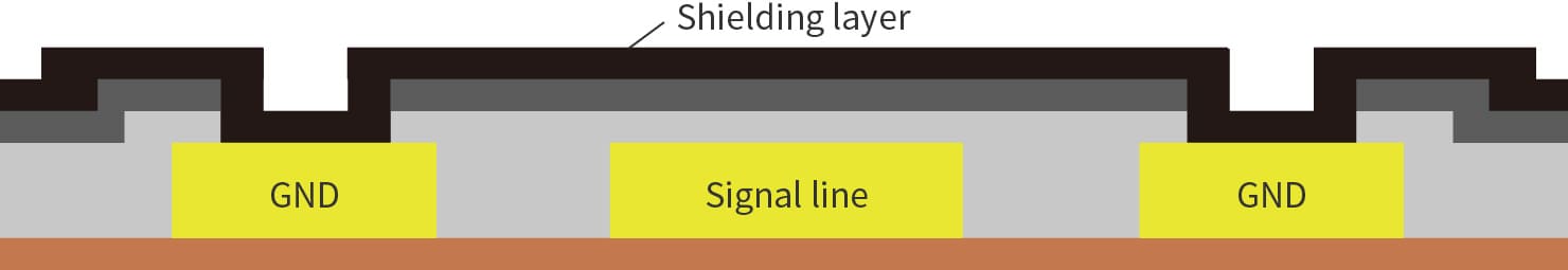
|
| Double-side shield |
Formed with 3-layer FPC
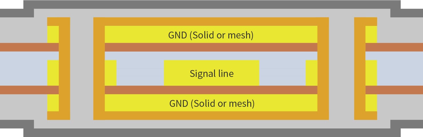
Formed with double-sided FPC + electromagnetic shielding layer 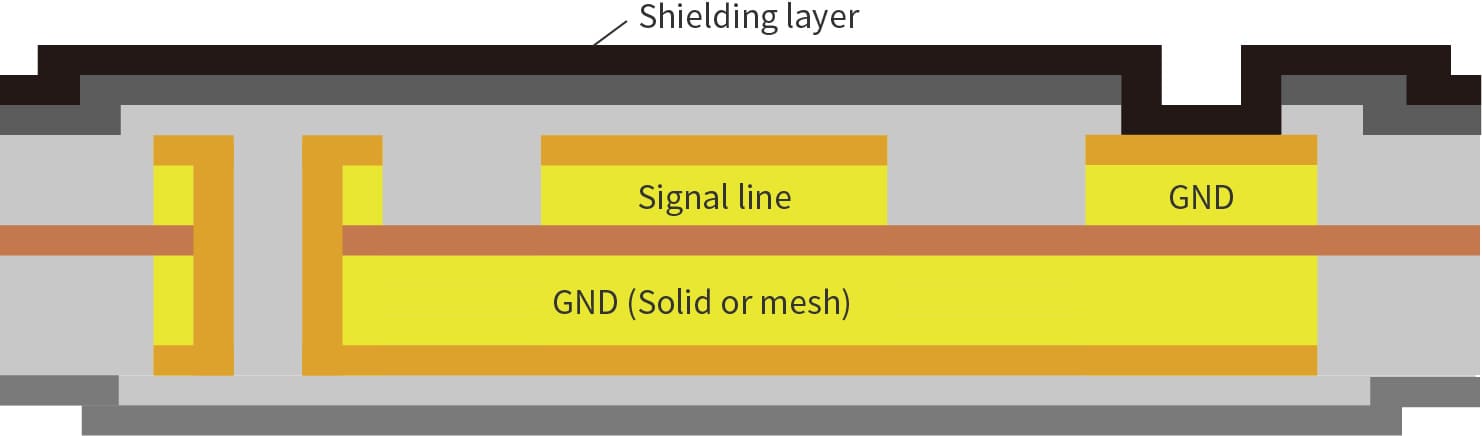
|
Heater FPC
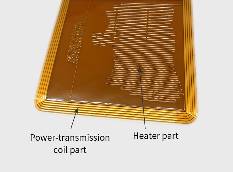
We have developed a wireless heater by integrating a wireless power-transmission coil and heater on an FPC.
In-vehicle sensors are equipped with heaters to prevent the performance being affected by condensation and snow in winter. The heater FPC that we have developed means there is no need to connect a power supply cable, helping to make assembly simpler for automotive manufacturers.
The coil part is thin and flexible, and the shape and temperature distribution of the heater part can be designed to any specification, so we can provide a solution to suit your requirements. The heater performance is affected by the power-transmission coil. We have achieved the thinnest and highest performance coil characteristics in the industry using FPC. Another feature of our new product is that the coil and heater are seamlessly integrated, making it highly reliable and water resistant. This makes it suitable for application in the growing fields of wearable devices and medical devices.
| Product developed by Fujikura Printed Circuits |
using Litz wire Conventional coil |
|
|---|---|---|
| Product thickness | 0.4mm | 1.3mm |
| Transmission output | 30W or more | |
| Transmission efficiency | 70% or more | |
 Wireless heater FPC
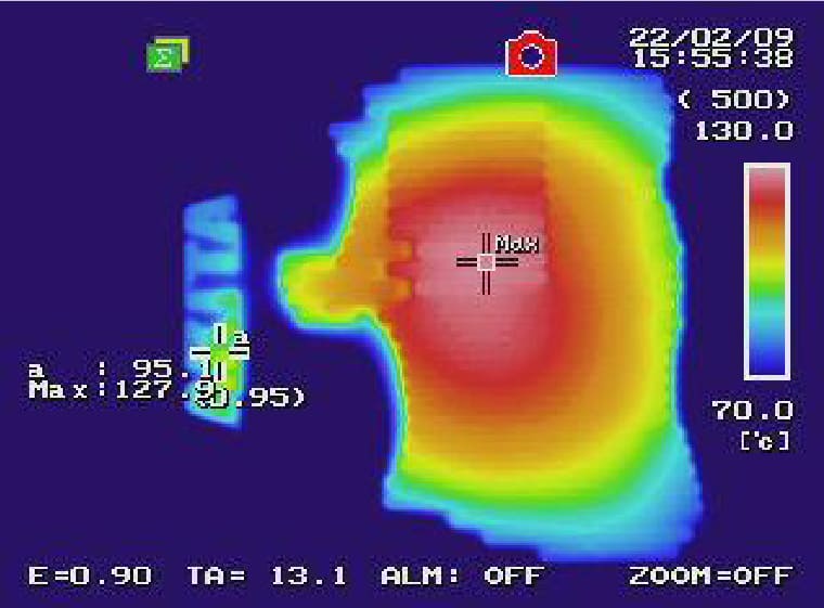 Thermography image
Thick copper FPC
Using thicker copper foil can improve heat dissipation and conduct higher currents. Fujikura Printed Circuits can provide FPCs using copper foil of thickness 150 µm.
Please contact us for detailed specifications.
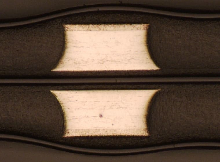 Cross section of a thick copper FPC
 (copper thickness>150 µm , Under R&D)
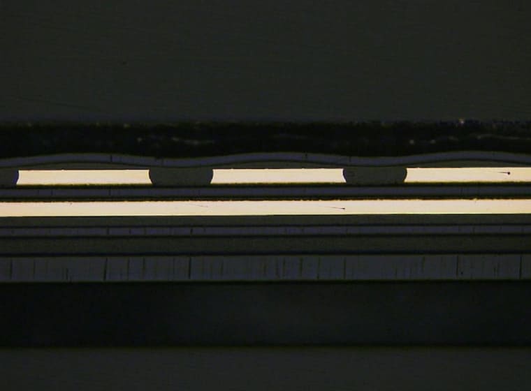 Cross section of a general FPC
 (copper thickness=30 µm)