TechnologyFujikura Printed Circuits technology
Fine pitch
We provide fine pitch FPCs using various process.
We can tailor a solution to your required specifications. Please contact us to discuss your requirements.
Subtractive process (circuit is formed by copper etching process.)
-
60 µm pitch
Line/Space =30um/30um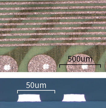
-
50 µm pitch
Line/Space =25um/25um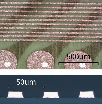
-
40 µm pitch
Line/Space =20um/20um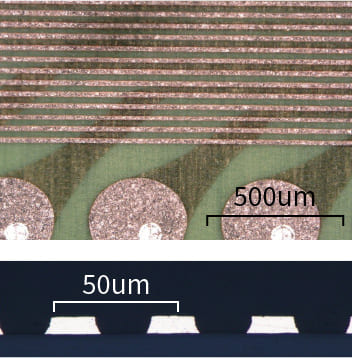
Semi-additive process(circuit is formed by copper plating)
-
60 µm pitch
Line/Space =30um/30um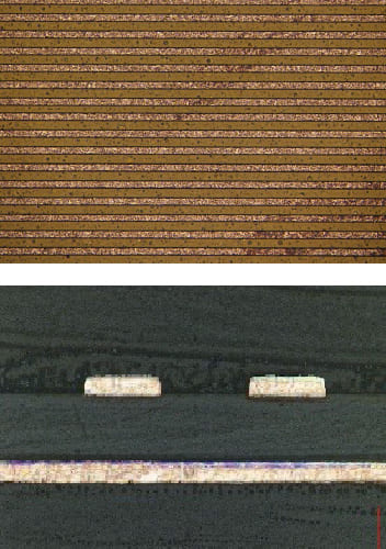
-
50 µm pitch
Line/Space =25um/25um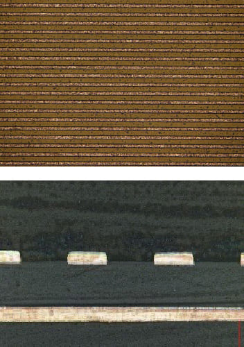
-
40 µm pitch
Line/Space =20um/20um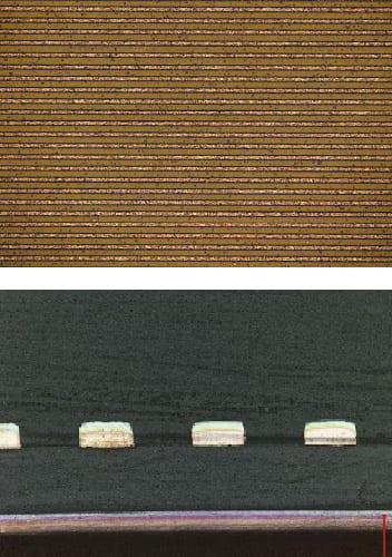
-
30 µm pitch
Line/Space =15um/15um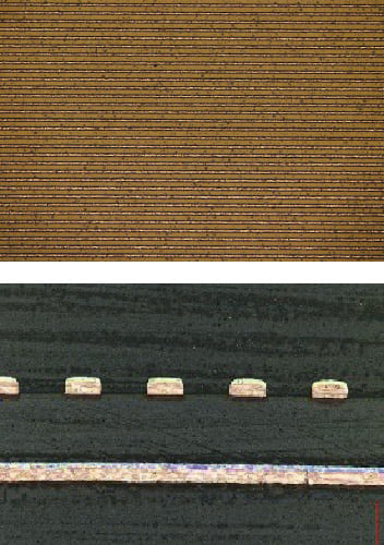
-
20 µm pitch
Line/Space =10um/10um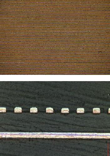
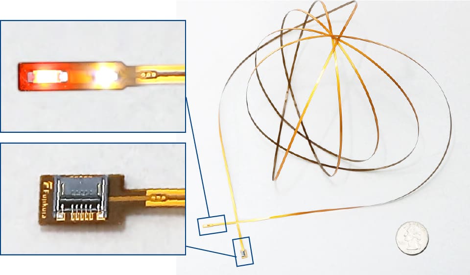
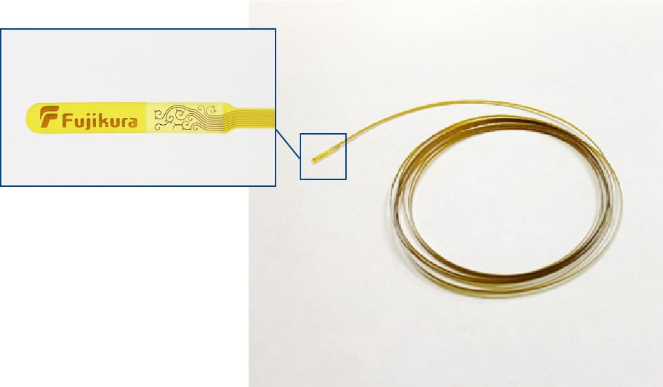
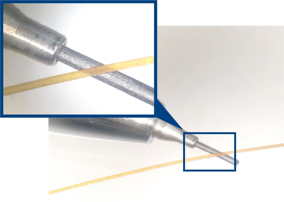
Long FPC
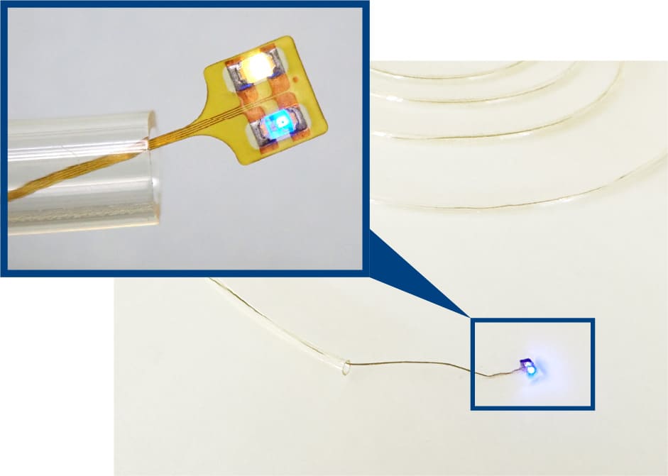
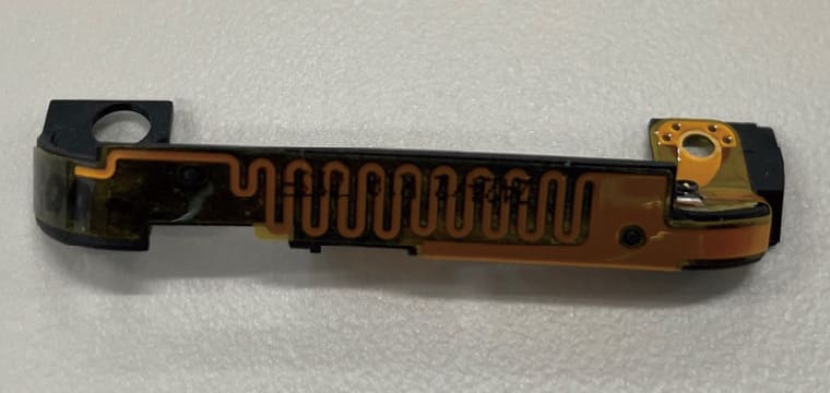
We have developed narrow width and long FPC over 2.0 m in length and less than 1.0 mm in width. Evaluation samples are now available. A circuit pitch of L/S=50 µm/50 µm is possible.
Narrow width and long FPCs can be used in place of cables in applications where space is limited, such as medical devices (endoscopes, catheters) or cameras for industrial endoscope. Please contact us to discuss your requirements.
Such equipment usually involves miniature cameras, sensors and LEDs on a substrate with multiple coaxial cables soldered to it. Replacing this with an narrow width and long FPC will reduce weight and allow for seamless structure with the components directly mounted, thus simplifying assembly.
| Evaluation sample specification | Under development | |
|---|---|---|
| FPC width | 1.0mm or more | Less than 1.0 mm |
| Wiring length | Less than 2.0 m | 2.0 m or more |
| Layers of wiring | Single-sided (1 layer), double-sided (2 layers) | Multilayer (3 layers) or more |
| L/S | 50 µm/50 µm or more | Less than 50 µm/50 µm |
High density mounting
We can supply single-sided, double-sided, and multilayer FPC with various components mounted.
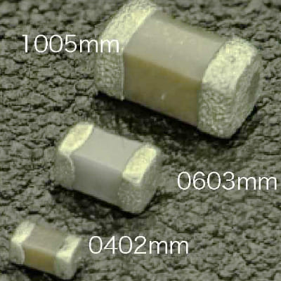
Features
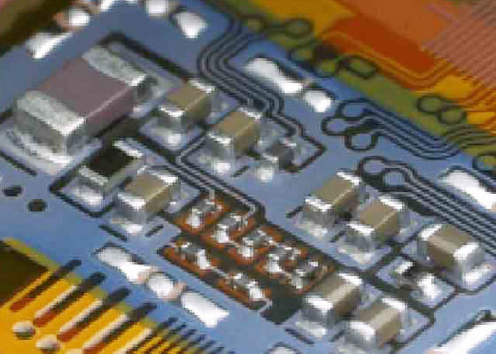
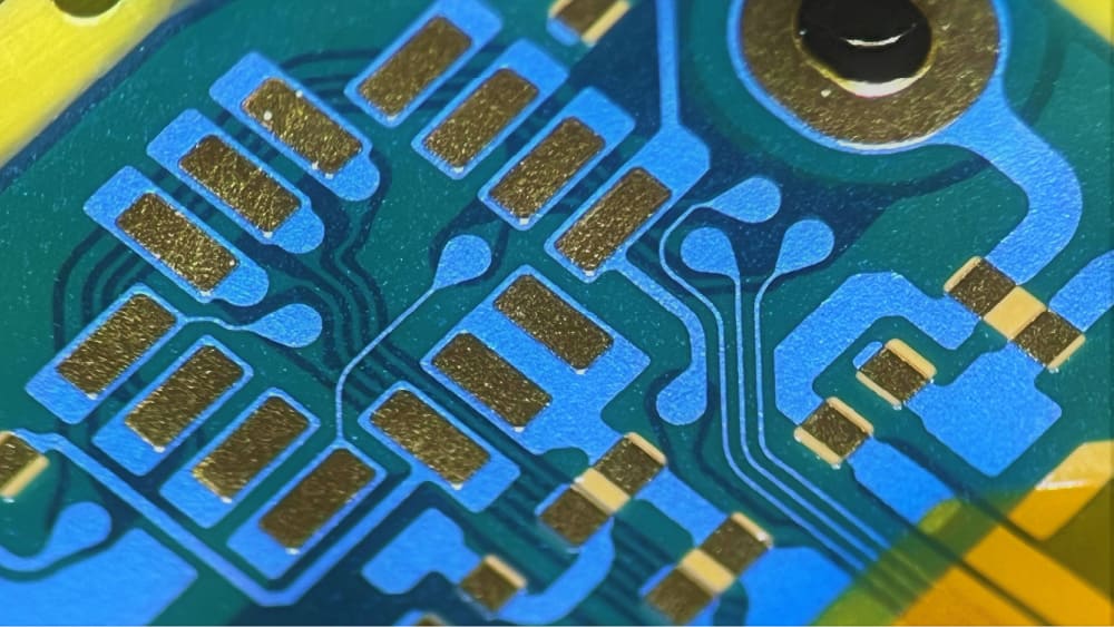
High density mounting of 0402 size chip components, 0.35-mm pitch fine pitch connectors, and 0.4-mm pitch BGA/CSP mounting. Please contact us to discuss smaller sizes and mounting pitch. We can also provide functions such as reinforcement/moisture proofing by applying resin coating to the mounted components. Our strength is that we can handle the full process from FPC design and manufacturing to mounting and assembly.
Different size chips Mixed mounting FPC
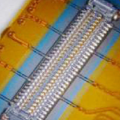
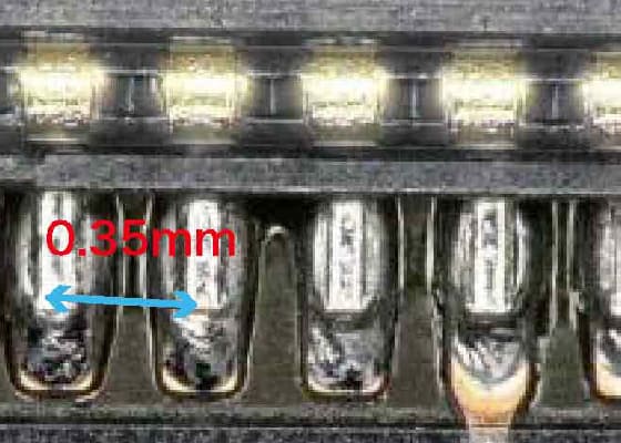
0.35 mm pitch B-B connector mounted FPC
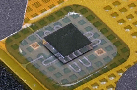
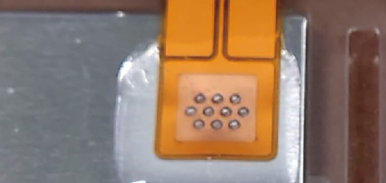
CSP mounted FPC
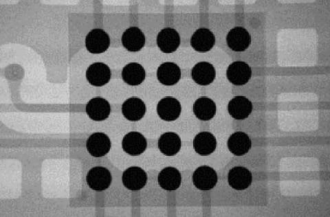
X-ray picture
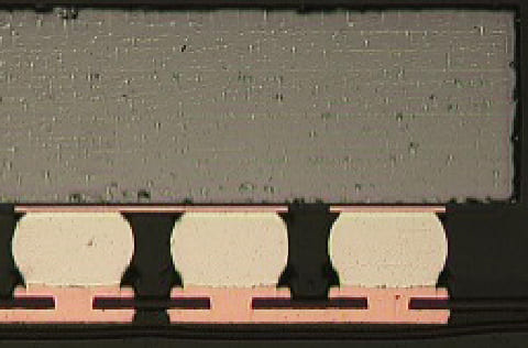
Cross section
Assembly (FPC post-processing)
Fujikura Printed Circuits can provide various post-processing for FPCs.
Please contact us for details.
Double-sided tape application process
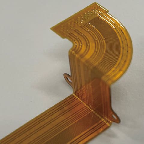
Bending process
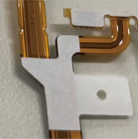
Laminating resin parts
FPC-aluminium plate connection (laser, Under R&D)
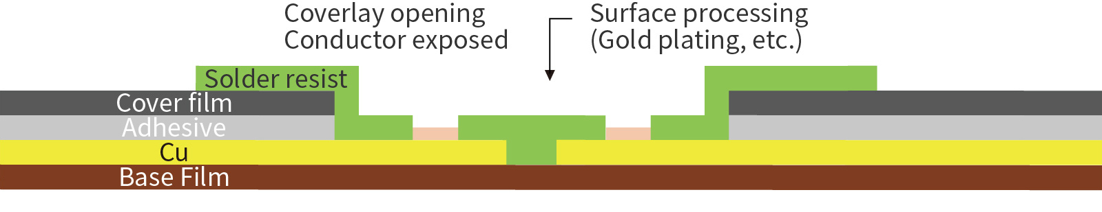
Solder resist
Solder resist is applied to the FPC by screen printing. It is then exposed through a patterned negative film and the uncured parts are removed with dilute alkaline liquid to form fine patterns and create pads for high-density mounting.
Structure
Functions
1.Protection from dust, heat, moisture, etc.
Solder resist protects circuit patterns from factors in the external environment, such as dust, heat, and moisture, which ensures long-term stable operation of electronic devices.
2.Maintaining electrical insulation between circuit patterns
As electronic devices become ever smaller, FPC wiring is getting finer. Solder resist maintains insulation between circuit patterns, preventing short circuiting.
High-precision outline cutting
In addition to outline cutting using conventional molding process, high-precision outline cutting is also possible using lasers. This allows processing of various products, such as ultra-fine, high-precision and long products, which were not possible with conventional blanking process. Please contact us to discuss whether a solution is possible.
Width 0.3 mm FPC